Pm Fiber Patch Cable

Leader Manufacturer of the Best Quality UPC fiber optic assemblies both in singlemode and multimode, simplex and duplex.
Click to Enlarge
Undamaged Fiber End
Damaged Fiber End
Laser Induced Damage in Silica Optical Fibers
The following tutorial details damage mechanisms in unterminated bare and terminated optical fibers, including damage mechanisms at both the air-to-glass interface and within the glass of the optical fiber. Please note that while general rules and scaling relations can be defined, absolute damage thresholds in optical fibers are extremely application dependent and user specific. This tutorial should only be used as a guide to estimate the damage threshold of an optical fiber in a given application. Additionally, all calculations below only apply if all cleaning and use recommendations listed in the last section of this tutorial have been followed. For further discussion about an optical fiber s power handling abilities within a specific application, contact Thorlabs Tech Support.
Damage at the Free Space-to-Fiber Interface
There are several potential damage mechanisms that can occur at the free space-to-fiber interface when coupling light into a fiber. These come into play whether the fiber is used bare or terminated in a connector.
Unterminated Silica Fiber Maximum Power Densities
Type
Theoretical Damage Threshold
Practical Safe Value
CW
Average Power
1 MW/cm2
250 kW/cm2
10 ns Pulsed
Peak Power
5 GW/cm2
1 GW/cm2
Unterminated Bare Fiber
Damage mechanisms in bare optical fiber can be modeled similarly to bulk optics, and industry-standard damage thresholds for UV Fused Silica substrates can be applied to silica-based fiber refer to the table to the right. The surface areas and beam diameters involved at the air-to-glass interface are extremely small compared to bulk optics, especially with single mode SM fiber, resulting in very small damage thresholds.
The effective area for SM fiber is defined by the mode field diameter MFD, which is the effective cross-sectional area through which light propagates in the fiber. A free-space beam of light must be focused down to a spot of roughly 80 of this diameter to be coupled into the fiber with good efficiency. MFD increases roughly linearly with wavelength, which yields a roughly quadratic increase in damage threshold with wavelength. Additionally, a beam coupled into SM fiber typically has a Gaussian-like profile, resulting in a higher power density at the center of the beam compared with the edges, so a safety margin must be built into the calculated damage threshold value if the calculations assume a uniform density.
Multimode MM fiber s effective area is defined by the core diameter, which is typically far larger than the MFD in SM fiber. Kilowatts of power can be typically coupled into multimode fiber without damage, due to the larger core size and the resulting reduced power density.
It is typically uncommon to use single mode fibers for pulsed applications with high per-pulse powers because the beam needs to be focused down to a very small area for coupling, resulting in a very high power density. It is also uncommon to use SM fiber with ultraviolet light because the MFD becomes extremely small; thus, power handling becomes very low, and coupling becomes very difficult.
Example Calculation
For SM400 single mode fiber operating at 400 nm with CW light, the mode field diameter MFD is approximately Ø3 µm. For good coupling efficiency, 80 of the MFD is typically filled with light. This yields an effective diameter of Ø2.4 µm and an effective area of 4.52 µm2:
Area πr2 π MFD/2 2 π 1.22 µm2 4.52 µm2
This can be extrapolated to a damage threshold of 11.3 mW. We recommend using the practical value maximum power density from the table above to account for a Gaussian power distribution, possible coupling misalignment, and contaminants or imperfections on the fiber end face:
250 kW/cm2 2.5 mW/µm2
4.25 µm2 2.5 mW/µm2 11.3 mW
Terminated Fiber
Optical fiber that is terminated in a connector has additional power handling considerations. Fiber is typically terminated by being epoxied into a ceramic or steel ferrule, which forms the interfacing surface of the connector. When light is coupled into the fiber, light that does not enter the core and propagate down the fiber is scattered into the outer layers of the fiber, inside the ferrule.
The scattered light propagates into the epoxy that holds the fiber in the ferrule. If the light is intense enough, it can melt the epoxy, causing it to run onto the face of the connector and into the beam path. The epoxy can be burned off, leaving residue on the end of the fiber, which reduces coupling efficiency and increases scattering, causing further damage. The lack of epoxy between the fiber and ferrule can also cause the fiber to be decentered, which reduces the coupling efficiency and further increases scattering and damage.
The power handling of terminated optical fiber scales with wavelength for two reasons. First, the higher per photon energy of short-wavelength light leads to a greater likelihood of scattering, which increases the optical power incident on the epoxy near the end of the connector. Second, shorter-wavelength light is inherently more difficult to couple into SM fiber due to the smaller MFD, as discussed above. The greater likelihood of light not entering the fiber s core again increases the chance of damaging scattering effects. This second effect is not as common with MM fibers because their larger core sizes allow easier coupling in general, including with short-wavelength light.
Fiber connectors can be constructed to have an epoxy-free air gap between the optical fiber and ferrule near the fiber end face. This design feature, commonly used with multimode fiber, allows some of the connector-related damage mechanisms to be avoided. Our high-power multimode fiber patch cables use connectors with this design feature.
Combined Damage Thresholds
As a general guideline, for short-wavelength light at around 400 nm, scattering within connectors typically limits the power handling of optical fiber to about 300 mW. Note that this limit is higher than the limit set by the optical power density at the fiber tip. However, power handing limitations due to connector effects do not diminish as rapidly with wavelength when compared to power density effects. Thus, a terminated fiber s power handling is connector-limited at wavelengths above approximately 600 nm and is fiber-limited at lower wavelengths.
The graph to the right shows the power handling limitations imposed by the fiber itself and a surrounding connector. The total power handling of a terminated fiber at a given wavelength is limited by the lower of the two limitations at that wavelength. The fiber-limited blue line is for SM fibers. An equivalent line for multimode fiber would be far above the SM line on the Y-axis. For terminated multimode fibers, the connector-limited red line always determines the damage threshold.
Please note that the values in this graph are rough guidelines detailing estimates of power levels where damage is very unlikely with proper handling and alignment procedures. It is worth noting that optical fibers are frequently used at power levels above those described here. However, damage is likely in these applications. The optical fiber should be considered a consumable lab supply if used at power levels above those recommended by Thorlabs.
Damage Within Optical Fibers
In addition to damage mechanisms at the air-to-glass interface, optical fibers also display power handling limitations due to damage mechanisms within the optical fiber itself. Two categories of damage within the fiber are damage from bend losses and damage from photodarkening.
Bend Losses
Bend losses occur when a fiber is bent to a point where light traveling in the core is incident on the core/cladding interface at an angle higher than the critical angle, making total internal reflection impossible.Under these circumstances, light escapes the fiber, often in one localized area. The light escaping the fiber typically has a high power density, which can cause burns to the fiber as well as any surrounding furcation tubing.
A special category of optical fiber, called double-clad fiber, can reduce the risk of bend-loss damage by allowing the fiber s cladding 2nd layer to also function as a waveguide in addition to the core. By making the critical angle of the cladding/coating interface higher than the critical angle of the core/clad interface, light that escapes the core is loosely confined within the cladding. It will then leak out over a distance of centimeters or meters instead of at one localized spot within the fiber, minimizing damage. Thorlabs manufactures and sells 0.22 NA double-clad multimode fiber, which boasts very high, megawatt range power handling.
Photodarkening
A second damage mechanism within optical fiber, called photodarkening or solarization, typically occurs over time in fibers used with ultraviolet or short-wavelength visible light. The pure silica core of standard multimode optical fiber can transmit ultraviolet light, but the attenuation at these short wavelengths increases with the time exposed to the light. The mechanism that causes photodarkening is largely unknown, but several strategies have been developed to combat it. Fibers with a very low hydroxyl ion OH content have been found to resist photodarkening. Other dopants, including fluorine, can also reduce photodarkening.
Germanium-doped silica, which is commonly used for the core of single mode fiber for red or IR wavelengths, can experience photodarkening with blue visible light. Thus, pure silica core single mode fibers are typically used with short wavelength visible light. Single mode fibers are typically not used with UV light due to the small MFD at these wavelengths, which makes coupling extremely difficult.
Even with the above strategies in place, all fibers eventually experience photodarkening when used with UV light, and thus, fibers used with these wavelengths should be considered consumables.
Tips for Maximizing an Optical Fiber s Power Handling Capability
With a clear understanding of the power-limiting mechanisms of an optical fiber, strategies can be implemented to increase a fiber s power handling capability and reduce the risk of damage in a given application. All of the calculations above only apply if the following strategies are implemented.
One of the most important aspects of a fiber s power-handling capability is the quality of the end face. The end face should be clean and clear of dirt and other contaminants that can cause scattering of coupled light. Additionally, if working with bare fiber, the end of the fiber should have a good quality cleave, and any splices should be of good quality to prevent scattering at interfaces.
The alignment process for coupling light into optical fiber is also important to avoid damage to the fiber. During alignment, before optimum coupling is achieved, light may be easily focused onto parts of the fiber other than the core. If a high power beam is focused on the cladding or other parts of the fiber, scattering can occur, causing damage.
Additionally, terminated fibers should not be plugged in or unplugged while the light source is on, again so that focused beams of light are not incident on fragile parts of the connector, possibly causing damage.
Bend losses, discussed above, can cause localized burning in an optical fiber when a large amount of light escapes the fiber in a small area. Fibers carrying large amounts of light should be secured to a steady surface along their entire length to avoid being disturbed or bent.
Additionally, choosing an appropriate optical fiber for a given application can help to avoid damage. Large-mode-area fibers are a good alternative to standard single mode fibers in high-power applications. They provide good beam quality with a larger MFD, thereby decreasing power densities. Standard single mode fibers are also not generally used for ultraviolet applications or high-peak-power pulsed applications due to the high spatial power densities these applications present.
Custom Patch Cable Manufacturing Area
at Thorlabs Newton, NJ Facility
Thorlabs stocks the largest selection of single mode and multimode optical fibers in the photonics industry. If our selection of stocked patch cables does not meet your needs, we also offer custom patch cable services. Please use the form below to build and order your custom cable. If you find your needs are not met by the options in the form below, please contact us and we will design a specialty cable to meet your needs.
Fast Turnaround Service
Need a cable right away to finish your project. If your order is placed before 2 PM EST and the total order request is for five or less SM or MM cables, each with a maximum individual length of 20 m, we will manufacture and ship them the same day PM cables ship in 2 days.
OEM Patch Cables
We offer scheduled deliveries, competitive pricing, account support, and kanban stocking agreements. Please contact us with any questions you may have so we can better meet your OEM needs.
Build Your Custom Patch Cable
Custom Cable Configurator
Step 1: Select Your Fiber Type
Please select Single Mode SM, Multimode MM, Polarization-Maintaining PM or Doped Fiber. Alternatively, enter the item number of the specific fiber you require. If you are unsure which fiber type will best meet your needs, please go to the Fiber Options tab for more information on each fiber option.SM PM MM Doped or Part Number: Part not found.
Step 2: Select Your Fiber
Step 3: Select Your Tubing
Preferred options will be noted with an asterisk
Step 4: Select Your Connectors
Preferred options will be noted with an asterisk Connector 1:
Connector 2:
Select your key alignment for Connector 1:
Preferred options will be noted with an asterisk Connector 1: Slow FastNone
Select your key alignment for Connector 2:
Preferred options will be noted with an asterisk Connector 2: Slow FastNone
Step 5: Select Your Length and QuantityLength: meters. Tolerance of 1 or 7 cm, Whichever is Greater
Quantity: The requested quantity is greater than.
Price and Shipping Information
A representative will follow up with you concerning volume pricing and lead time.
Notes:
If your order is placed before 2 PM EST and the request is for five or less total order SM or MM cables, each with a maximum individual length of 20 m, we will manufacture and ship them the same day PM cables ship in 2 days.
The pricing above reflects the choices made in the form. If you require greater tolerances or any other specialty request, please contact us contains all selections made in form and we will be happy to speak with you as to how we can best meet your needs.
Contact UsPlease use the Special Request web form below to send us your request for your custom patch cable.Please Login if you have an account with us. First Name: Last Name: Company: Address: Address: City:
State/Province: Zip/Postal Code: Country: Phone: Fax: Email: Security Code: This code is to prevent automated spamming of our website. Thank you for your understanding.
Please click here if you cannot read the security image
Indicates required fieldFiber : None selected
Tubing : None selected
Connector 1 : None selected
Connector 2 : None selected
Connector 1 Alignment : None selected
Connector 2 Alignment : None selected
Length : None entered
Quantity : None entered
Fiber Optic Cable Structure
Fiber Cable Video
Click Image to Replay
General Fiber Information
A fiber optic cable is made of 5 main parts, labeled in the figure to the right. The core, made of glass or plastic, provides the path for light propagation. Larger core sizes allow a larger amount of light, or a larger beam diameter, to enter the fiber. The numerical aperture NA of the core determines the range of incident angles the fiber can accept and still perform within its specified range. The cladding prevents light from exiting the core and being absorbed by the rest of the cable. The coating, or buffer, protects the core and cladding and provides strength. The next layer of the cable is a material, such as Kevlar, that provides strength to the cable and helps prevent damage due to stress. The entire package is then encased in a jacket. This outer jacket provides one last layer of protection and also adds strength to the fiber. The jacket is typically colored to help the user determine what type of optical fiber is in the cable.
Thorlabs follows the industry standard in jacket coloration. We use a yellow jacket for our Single Mode SM fibers, a orange jacket for our Multimode MM fibers, and a blue jacked for our Polarization Maintaining PM fibers. Our custom patch cables can be made with any jacket color / fiber combination.
Patch Cable Inspection at Thorlabs in Newton, NJ
Building Your Custom Patch Cable
Have you looked through our broad selection of stocked patch cables to see if one of them meets your needs. If none of the stocked options are what you are looking for, a custom cable can be manufactured.
Select a Fiber
Thorlabs offers four major types of fiber: Single Mode SM, Multimode MM, Polarization Maintaining PM, and Doped. Each fiber type is explained in detail below. You will also find a complete list of all the fibers that we offer for our custom patch cables along with key specifications that may help you decide which fiber is best for your application. We sell all of these fibers individually on our website as well, along with a wide variety of others. Click here to view all of the fiber options Thorlabs offers. Please contact Tech Support if you have any other questions about our fiber.
Single Mode Video
Light Propagation Down Single Mode Fiber
Single Mode SM Fiber
SM fiber has small core sizes that only allow one mode, or ray, to propagate through the fiber. The mode defines how the light travels through space. Light propagates along the axis of the fiber in this single mode see drawing to the right. In SM fiber, waves have the same mode but different frequencies. This type of fiber is useful in situations where the integrity of the incident pulse of light needs to be retained over long distances. SM fiber offers high bandwidth and low modal dispersion.
Photosensitive SM Fiber
Photosensitive single mode fiber is designed to provide high photosensitivity for UV radiation. These fibers offer lower splice loss than standard SM fibers and are suitable for a range of applications. For more information about these fibers, click here.
Photosensitive SM Fiber Options
Item
Wavelength Range
NA
MFD
PS1060
980 - 1060 nm
0.13
6.2 0.8 µm 1060 nm
GF3
1500 - 1600 nm
0.16
10.5 0.8 µm 1550 nm
GF1
9.3 0.5 µm 1310 nm
GF4A
1550 nm
4.4 0.2 µm 1550 nm
GF1B
10.4 0.8 µm 1550 nm
SM300
320 - 430 nm
0.12 - 0.14
2.0 - 2.4 µm 350 nm
S405-XP
400 - 680 nm
0.12
3.3 0.5 µm 405 nm
4.6 0.5 µm 630 nm
460HP
450 - 600 nm
3.5 0.5 µm 515 nm
630HP
600 - 770 nm
4.0 0.5 µm 630 nm
SM600
633 - 780 nm
0.10 - 0.14
3.6 - 5.3 µm 633 nm
S630-HP
630 - 860 nm
4.2 0.5 µm 630 nm
780HP
780 - 970 nm
5.0 0.5 µm 850 nm
SM800-5.6-125
830 - 980 nm
4.7 - 6.9 µm 830 nm
SM800G80
0.14 - 0.18
3.75 - 4.9 µm 830 nm
SM980-5.8-125
980 - 1550 nm
0.13 - 0.15
5.3 - 6.4 µm 980 nm
HI1060-J9
0.14
5.9 0.3 µm 980 nm
6.2 0.3 µm 1060 nm
1060XP
980 - 1600 nm
5.9 0.5 µm 980 nm
6.2 0.5 µm 1060 nm
9.5 0.5 µm 1550 nm
980HP
0.20
4.2 0.5 µm 980 nm
6.8 0.5 µm 1550 nm
SM980G80
0.17 - 0.19
4.2 - 4.9 µm 980 nm
SMF-28-J9
1260 - 1625 nm
9.2 0.4 µm 1310 nm
10.4 0.5 µm 1550 nm
CCC1310-J9
8.6 0.4 µm 1310 nm
9.7 0.5 µm 1550 nm
1310BHP
1300 - 1625 nm
8.6 0.5 µm 1310 nm
SM1250G80
1310 - 1550 nm
0.11 - 0.13
8.2 - 9.9 µm 1310 nm
1550BHP
1460 - 1620 nm
SM1500G80
1520 - 1650 nm
0.19 - 0.21
6.0 - 6.8 µm 1550 nm
SM2000
1700 - 2300 nm
0.11
13 1 µm 1996 nm
Cladding: Ø80 µm
Ø900 µm Jacket
Ultra High NA SM Fiber Options
UHNA1
1100 - 1600 nm
0.28
4.0 µm 1310 nm
UHNA3
960 - 1600 nm
0.35
3.3 µm 1310 nm
UHNA4
Step Index Video
Light Propagation Down Step-Index Multimode Fiber
Graded-Index Video
Light Propagation Down Graded-Index Multimode Fiber
Multimode MM Fiber
The larger core diameters of multimode MM fiber allow for the propagation of more than one mode. Light not only propagates along the axis of the fiber, as in SM fiber, but also travels away from the axis toward the cladding see animations to the right. The total internal reflection that occurs at the core-cladding boundary helps reflect the light back towards the fiber axis. MM fiber tends to have a higher NA and larger core sizes than SM fiber, which allows it to gather larger beams of light at greater incident angles. It has lower bandwidth than SM fiber and is susceptible to modal dispersion.
Modal dispersion is a distortion of the incident light pulse caused by the fact that the propagation velocity of the different modes varies. Due to the zigzag path the modes take to travel down the fiber, the modes that zigzag more take longer to reach the end than those that travel in a straighter path. When all modes, both fast and slow, combine again at the other end of the fiber, the pulse is widened.
There are two main types of MM fiber: Step Index and Graded Index. The core in a step-index fiber has a uniform refractive index throughout. There is a sharp decrease in refractive index at the core-cladding boundary where the cladding refractive index is lower than that of the core. This results in the modes traveling down the fiber in a very jagged path see animation to the right. Step-index fiber is generally made by doping the fiber with another material.
The refractive index of the core in a graded-index fiber decreases as the distance to the center of the core increases. This results in a much smaller change in the refractive indice at the core-cladding interface. The smoother transition causes the modes to travel in sinusoidal paths down the fiber see animation to the right. Graded-index fibers have much lower modal dispersion than step-index fibers. The parabolic wave profile of the modes continuously re-focuses the rays. Those traveling straight down the center of the fiber travel much slower than those traveling in a more sinusoidal path due to the differences in refractive index. The resulting pulse is less spread out and very close in profile to the incident one.
Solarization-Resistant MM Fiber
Solarization-Resistant multimode fiber exhibits impressive performance and transmission from the UV to the NIR 180 to 1150 nm. With exceptional UV radiation resistance compared to standard fibers, these multimode fibers are ideal for use in applications such as spectroscopy for pollution analysis and chemical processing, UV photolithography, and medical diagnostics. The polyimide buffer allows this fiber to be used at temperatures up to 300 C. For more information about these fibers, click here.
Graded-Index MM Fiber Options
Core Size
GIF50C
750 - 1450 nm
0.20 0.015
50.0 2.5 µm
GIF625
800 - 1350 nm
0.275 0.015
62.5 2.5 µm
Solarization Resistant Step-Index MM Fiber Options
Small Core Step-Index MM Fiber Options
HPSC10
400 - 550 nm and
700 - 1400 nm
0.100 0.015
10 3.0 µm
HPSC25
25 3.0 µm
Polarization-Maintaining PM Fiber
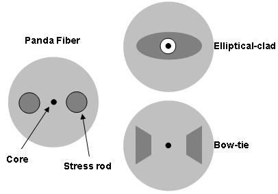
The polarization of incident light is maintained during propagation through polarization-maintaining PM fiber. There are many types of PM fibers, but they all work the same way: stress is induced in the core via rods within the cladding. The stress aligns the fiber, and the light, to a particular polarization. Thorlabs offers two types of PM fiber: Panda style and Bow-Tie style. The types are named for the shape of the stress rods incorporated into the fiber see drawing to the right. PM fiber is used in fiber optic sensing, interferometry, and quantum key distribution. It is also commonly found in telecommunications applications connecting a laser source and a modulator. PM fiber has higher attenuation than SM and MM fibers.
It is important to note PM fiber does not polarize the incident light; rather, it just maintains the existing polarization of the light that is aligned with the stress rods. The fiber key is aligned during the manufacturing process to ensure high-quality output, as evidenced by the polarization extinction ratio PER. A higher PER indicates that the light exiting the fiber has a polarization that is more consistent with that of what entered.
Bow-Tie Style PM Fiber Options
Wavelength
HB800G
830 nm
3.7 - 4.9 µm 830 nm
HB980T
980 nm
5.3 - 6.4 µm 980 nm
HB1250T
1310 nm
8.1 - 9.9 µm 1310 nm
HB1500T
9.6 - 11.7 µm 1550 nm
Photosensitive PM Fiber Options
PS-PM980
10.4 0.8 µm 1550 nm
Panda Style PM Fiber Options
PM460-HP
460 - 700 nm
3.3 0.5 µm 515 nm
PM630-HP
620 - 850 nm
4.5 0.5 µm 630 nm
PM780-HP
770 - 1100 nm
5.3 1.0 µm 850 nm
PM980-XP
970 - 1550 nm
6.6 0.7 µm 980 nm
PM1300-XP
1270 - 1625 nm
9.3 0.5 µm 1300 nm
PM1550-XP
1440 - 1625 nm
0.125
9.9 0.5 µm 1550 nm
PM2000
1850 - 2200 nm
8.0 µm 1950 nm
Pure Silica Core
PM-S350-HP
350 - 460 nm
2.3 µm 350 nm
PM-S405-XP
HB830Z
4.1 - 7.7 µm 830 nm
HB1060Z
1064 nm
6 - 8 µm 1064 nm
HB1550Z
0.09 - 0.11
10.0 - 12.5 µm 1550 nm
Operating
Wavelength
SHB1250G80
0.13 - 0.17
6.2 - 8.4 µm 1310 nm
SHB1250
SHB1500
0.13 - 0.16
7.9 - 9.9 µm 1310 nm
Doped Fiber
Erbium-Doped SM Fiber Options
Peak Core Absorption
ER16-8/125
16 3 dB/m
9.5 0.8 μm 1550 nm
ER30-4/125
30 3 dB/m
0.2
6.5 0.5 μm 1550 nm
ER80-8/125
80 8 dB/m
9.5 0.8 μm 1550 nm
ER110-4/125
110 10 dB/m
C-Band Fiber
M5-980-125
4.5 - 5.5 dB/m 980 nm
5.4 - 7.1 dB/m 1531 nm
0.21 - 0.24
5.5 - 6.3 µm
1550 nm
L-Band Fiber
M12-980-125
11.0 - 13.0 dB/m 980 nm
16.0 - 20.0 dB/m 1531 nm
5.7 - 6.6
Designed to operate at 1530 nm
Designed to operate from 900 - 970 nm
Erbium-Doped SM Fiber
Our wide range of highly doped erbium fibers are suitable for fiber lasers and amplifiers operating in the 1530 to 1610 nm wavelength region. These fibers are utilized in a broad range of applications, ranging from telecommunication amplifiers EDFAs to high-power PON/CATV boosters and ultra-short pulse amplifiers used in instrumentation, industrial, and medical applications. For more information about these fibers, click here.
Ytterbium-Doped MM Fiber
Thorlabs offers state-of-the-art Ytterbium doped optical fibers for optical amplifiers, ASE light sources, and high-power pulsed and CW fiber laser applications. These fibers are fabricated using the latest doped fiber production technology. For more information about these fibers, please click here.
Ytterbium-Doped PM Fiber
Thorlabs Ytterbium-doped PM fiber is manufactured using the latest technology. These fibers offer high birefringence, low nonlinear effects, and low photodarkening. For more information about these fibers, click here.
Passive Double Clad Fiber
Thorlabs passive large-mode-area LMA fibers are matched to the core diameters and numerical apertures of their active counterparts to maintain excellent beam quality throughout fiber laser or amplifier systems. The outer cladding diameter is designed to round the shaped active fibers, thereby achieving low pump coupling loss from passive to active fibers. The passive fibers are coated with low-index fluoroacrylate enabling active fibers to be pumped through them. For more information about these fibers, click here.
Choose a Connector
A connector terminates the end of an optical fiber and enables quick, easy connection and disconnection. The connectors mechanically couple and align the cores of the fibers so that light can pass from one to the other unobstructed. Thorlabs offers a flat-cleave option as well as 6 narrow key connectors for our Custom Patch Cables.Flat-Cleave
A flat-cleave is a carefully controlled break in the fiber perpendicular to the fiber axis, resulting in a flat end face. No connector is attached to the fiber. A flat-cleave allows for bare fiber connection. Flat-Cleaves are ideal for mechanical or fusion splicing or free space applications without the use of a connector.Scissor Cut
A scissor cut is a very quick cut that will not produce an even output or splice surface on the end of the fiber. This cut is ideal for the user who is proficient in cleaving fibers or intend to terminate a fiber with their own connector. The end of a scissor cut fiber must be cleaved and connectorized before it can be used.FC/PC Connectors
The threaded FC/PC connector is designed for high vibration environments. The PC stands for physical contact because this connector allows the fibers surfaces to be in direct contact with each other at the connector interface. The ceramic or stainless steel ferrule, or end, of an FC/PC connector is spring loaded to control the force on the fiber as the connector is screwed into its port. All of our FC/PC connectors offer a minimum back reflection of -40 to -45 dB.
Single Mode FC/PC Connectors
Our single mode SM FC/PC connector features a pre-radiused R20 mm ceramic ferrule to help minimize back reflections. The SM FC/PC connector has a hole size tolerance of 1/-0 µm and a maximum concentricity of 1 µm.
Multimode FC/PC Connectors
Our multimode MM FC/PC connector has a precision-drilled bore to match the fiber diameter and a maximum concentricity of 3 µm.
Polarization-Maintaining FC/PC Connectors
For Polarization-Maintaining PM fibers, we offer a FC connector with a continuously adjustable key to allow you to rotate the back of the connector to align to the slow or fast axis of the fiber. Once the connector is aligned, you can lock it in place with a drop of superglue. If you purchase a PM fiber cable that is aligned by us, the connector key will be aligned to your specification.FC/APC Connectors
This connector has the same basic design as the FC/PC connector, but the fiber end is polished at an angle. This Angled Physical Contact APC interface prevents light reflected at the fiber-fiber junction from traveling back up the fiber. FC/APC connectors only mate properly with other FC/APC connectors. Mating FC/APC with any other connector results in high insertion loss. These connectors minimize back reflections but have a higher insertion loss than their FC/PC counterparts.
All of our FC/APC connectors offer a minimum back reflection of -65 dB due to the nature of the APC end. Thorlabs APC connectors are distinguished by the use of a green strain relief boot.SMA Connectors
Our subminiature version A SMA connectors are used for large core, multimode fibers. These connectors are threaded like our FC/PC and FC/APC connectors. We stock SMA connectors for fibers with cladding diameters ranging from 125 to 1580 µm.ST Connectors
Straight Tip ST connectors have a bayonet-style mount that allows for quick connects and disconnects but does not seat the fiber as well as other connections.
Our single mode SM ST connector features a ceramic ferrule with a pre-radiused tip R20 mm to minimize back reflections. The ST connectors feature a concentricity of maximum 1 µm.
We also carry ST-style connectors designed for multimode MM applications. Our standard connectors have a bore size of 140 µm but we also carry a full supply of drilled conectors to meet custom requirements. These connectors feature a maximum concentricity of 1 µm.SC Connectors
Subscriber Connector SC connectors are snap-in connectors that are easy and quick to use. Out SC-style connectors, which have a bore size of Ø125 µm., feature a pre-radiused R20 mm ceramic ferrule to help minimize back reflections.LC Connectors
Lucent Connectors LC are similar to SC connectors but contain ferrules that are half the size of those found on SC connectors. We stock LC connectors for single mode fibers. Multimode LC connectors are available upon request. Due to their small size, they are ideal for situations where a large number of connectors are used in a small space.
Shop for fiber optic patch cables. Same day shipping. 45-day return policy. Free Technical Support 24/7.
Fiber Optic Distributor of communication fiber optic products. We sell all products Fiber Optics.
The LC fiber patch cables use a 1.25 mm ferrule, half the size of the ST patch cable. The LC fiber patch cable.
Fiber Optic Cable Products supplies Patch cables, splice on pigtails, attenuators, mtp mpo cable assemblies, multi fiber for single mode, and multimode fiber types.
Leader Manufacturer of the Best Quality APC fiber optic assemblies both in singlemode and multimode, simplex and duplex.
Rack Mount Fiber Patch Panel, Wall Mount Fiber Optic Patch Panel, Outdoor Fiber Splice Closure, Indoor Fiber Optic Enclosure, Vertical Cable Management, Horizontal.
FO4SALE offers the most complete selection and great quality fiber optic patch cables. Choose from SC, LC, ST, FC, MTRJ, MTP, E2000 and even 3M Volition VF-45 OS2.

Use this handy tool to quickly find the exact Fiber cable you need.
Fiber Optic Patch Cable
Fiber Optic Pigtail
Singlemode Fiber Optic Cable
10 Gigabit Fiber Optic Cable
Fan Out Kits
Multimode Fiber Optic Cable
Rack Mounts
Adapter Panels
Wall Mounts
Accessories - Cable Management
Workstations
Cassette Modules
Epoxy and Polish Connectors
Quick Termination Connectors
Adapters
Attenuators
Cleaning Supplies
Kits
Epoxy Products
Polish Equipment
Polish Film
Media Converters
Fiber Splicing Accessories
Cleavers
Fusion Splicers
Fusion Splice-On Connectors
Outdoor Closures
Splice Closure Accessories
Equipment
Light Sources, Power Meters, Test Kits
Fiber Identifier, Talk Sets, VFL
Inspection Scopes and Probes
Fiber Optic OTDR
Test Equipment Accessories
Hand Tools
Tool Kits
Cable Marking.